On-Axis Profiles
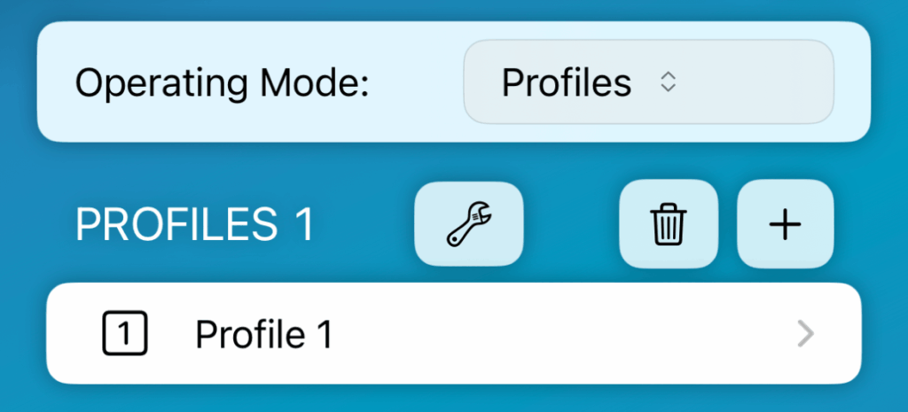
Profile Mode

The purpose of the On-Axis Profile function is to draw a uniform plane to the speaker’s axis, starting from the speaker’s rigging point and ending at the farthest point of the audience area. The idea is to create a separate On-Axis Profile for each speaker group (for example: Main, Side, 270). The primary purpose is to produce as accurate model as possible of the profile of the venue along the axis of the speaker. To be clear, we are only modeling what happens on the axis of the speakers, and not creating a complete 3D model of the venue. This is an advanced workflow designed for the most demanding conditions and requires its user to understand the three-dimensional challenges of speaker system coverage.
Measure Profile

Step 1 – Set the position of the instrument
Step 2 – Measure and enter values


Adjust Parameters
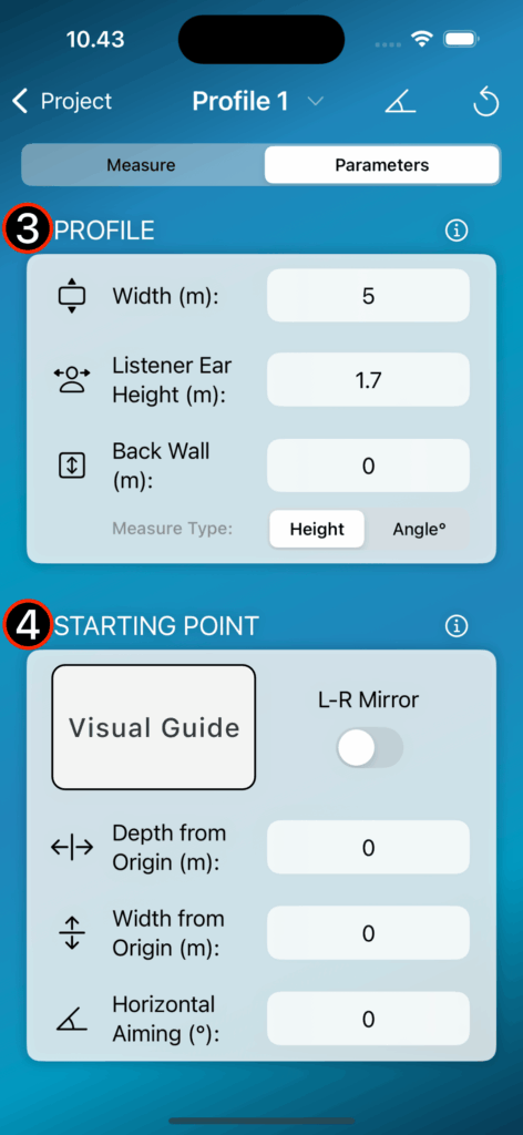
Step 3 – Modify the basic parameters if needed
Step 4 – Define the profile starting point relative to the zero point (origin) of the simulation program
Note
Back Wall can be used as ”ArrayProcessing Wall” or for overshooting purposes with autosplay feature.


Related Video Instructions
Create On-Axis Profiles From Design File
The On-Axis application is able to read the speaker group names and positions from the supported design file which can be used to create the On-Axis Profiles. When the position data is imported, profiles are drawn directly to the correct location in the simulation program.

Step 1 – Select Source File
When the operation mode of the app is set to profiles, an import button appears in the upper corner with which you can import the design file. Check the supported file formats from the compatibility chart.

Step 2 – Map
Map which source is assigned to which profile.
Step 3 – Select Main Speaker Group
Choose your ”Main” stereo system from the dialog box. One wide profile is drawn for the selected system.
Step 4 – Create On-Axis Profiles
Create profiles from data.
