Planes
Planes Mode
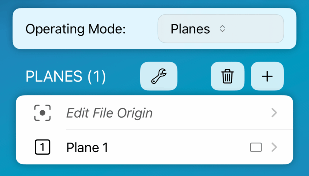

In Planes operation mode, audience areas are created in the traditional way, where all dimensions of each plane are entered manually. However, this mode has features that speed up the process, such as the ability to continue the plane automatically from the previous one. Multiple planes can be created from the plus button. Tap to edit and long press the row for rename and options.
Measure Plane
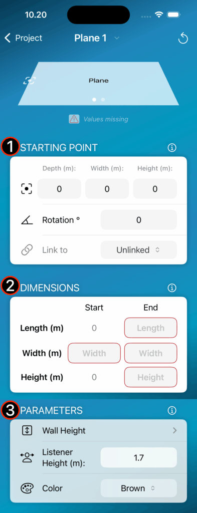
Step 1 – Define the starting point
Step 2 – Dimensions
Step 3 – Modify parameters
Note
Back Wall can be used as ”ArrayProcessing Wall” or for overshooting purposes with autosplay feature.


Multi File Export
Planes mode has a feature where each plane can be exported as a separate file. This is very useful, for example, in situations where the dimensions of different rooms are measured in the same project, but exported as separate files. For example, in an AV installation project, there may be several rooms for which you want a separate simulation file, but you want to measure them on-site for the same On-Axis project.
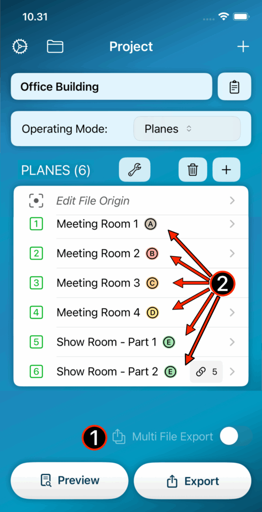
Step 1 – Enable multi file export function
Step 2 – Planes are organized into export groups
